“You can’t rely on bringing people downtown; you have to put them there” - Jane Jacobs (Death and Life of Great American Cities)
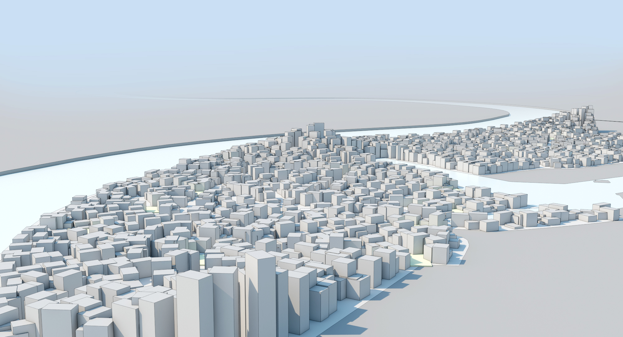
This project is directed to generate urban form using qualitative control over the experience of the urban dweller. The design method is focused on the creation of a pedestrian network by introducing detours for the main streets and evaluating them in the digital environment. Early experiments have resulted in a completely random distribution of building blocks fitting into defined pedestrian pathways with no distinct formal variation. In order to create more formal variation while maintaining control over the quality of the urban space, sectional typologies are used, giving rise to a new way of attaining urban morphologies and emergent pathways. The urban fabric was generated using central London’s density as target. Through computational means, the relationships of quality, intensity, and interactivity of different flows on site are applied to produce novel spatial organisations at the urban scale.
“A city that out-distances man’s walking powers is a trap for man” - Arnold Toynbee
“A city that out-distances man’s walking powers is a trap for man” - Arnold Toynbee

Site Anchor Points
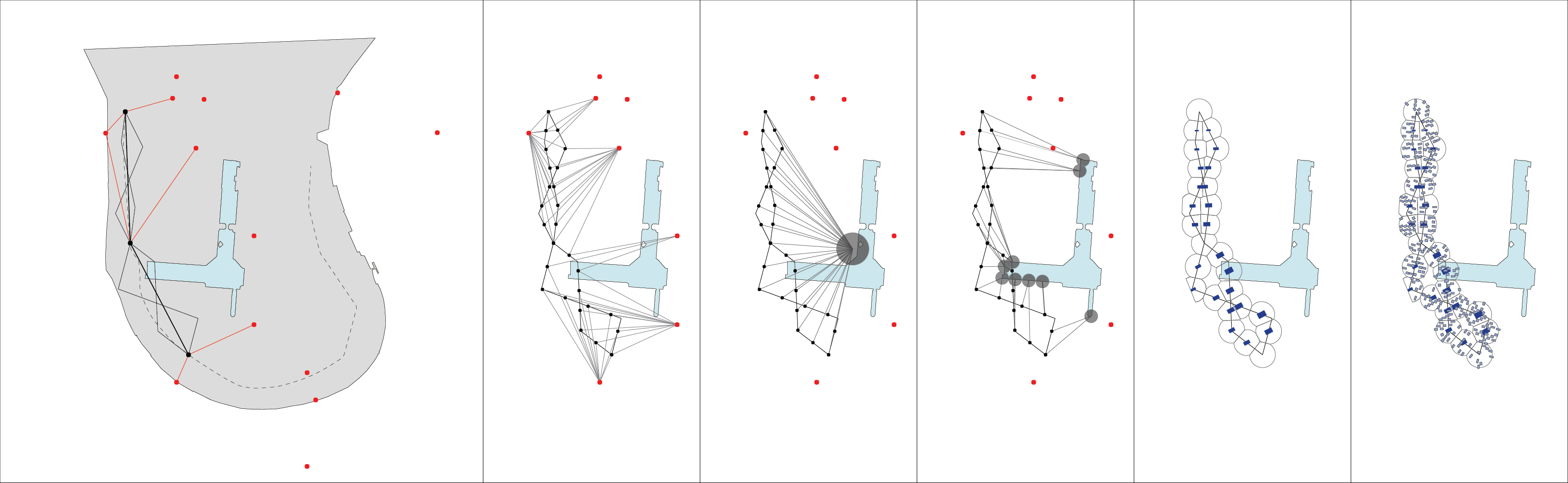
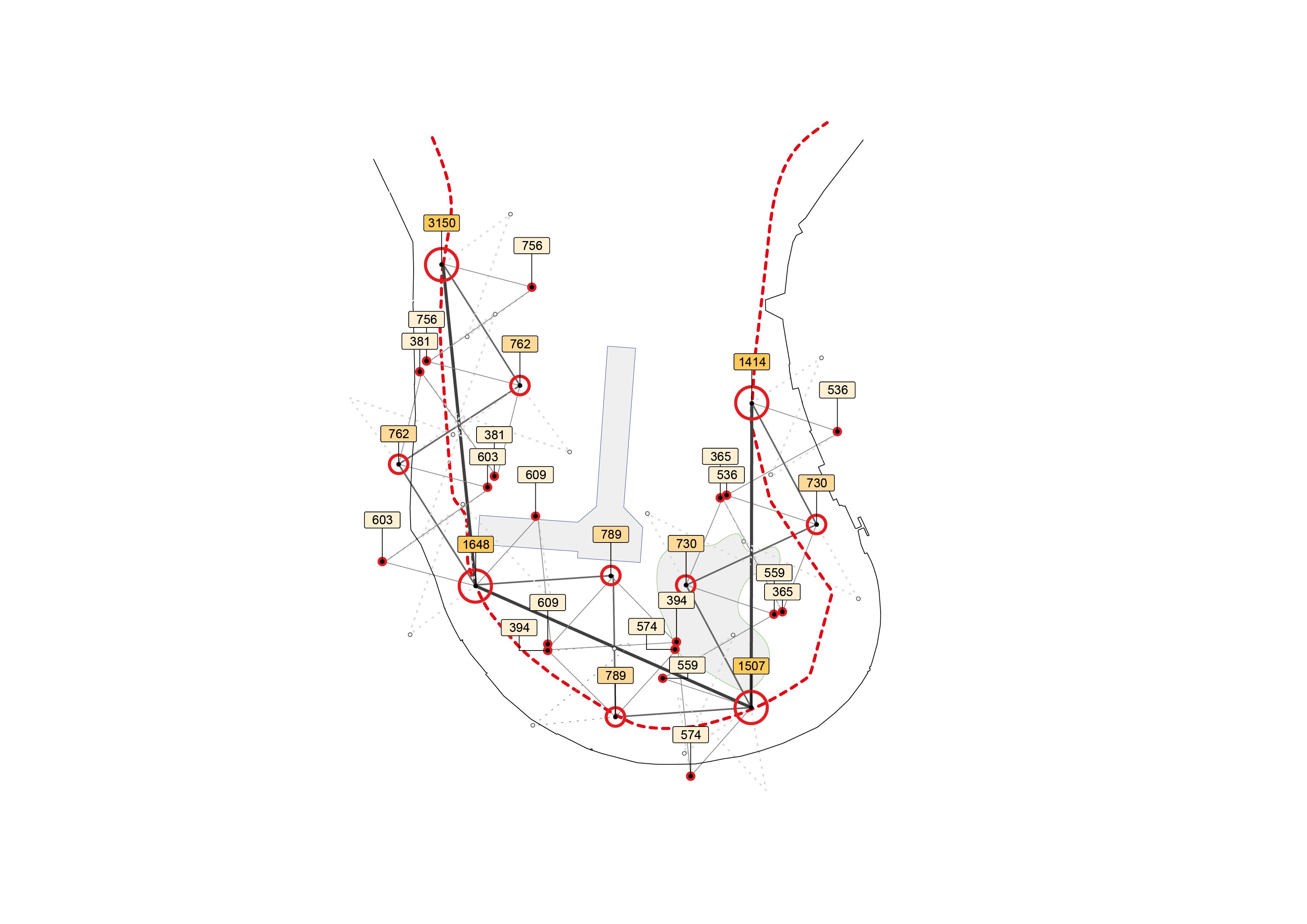
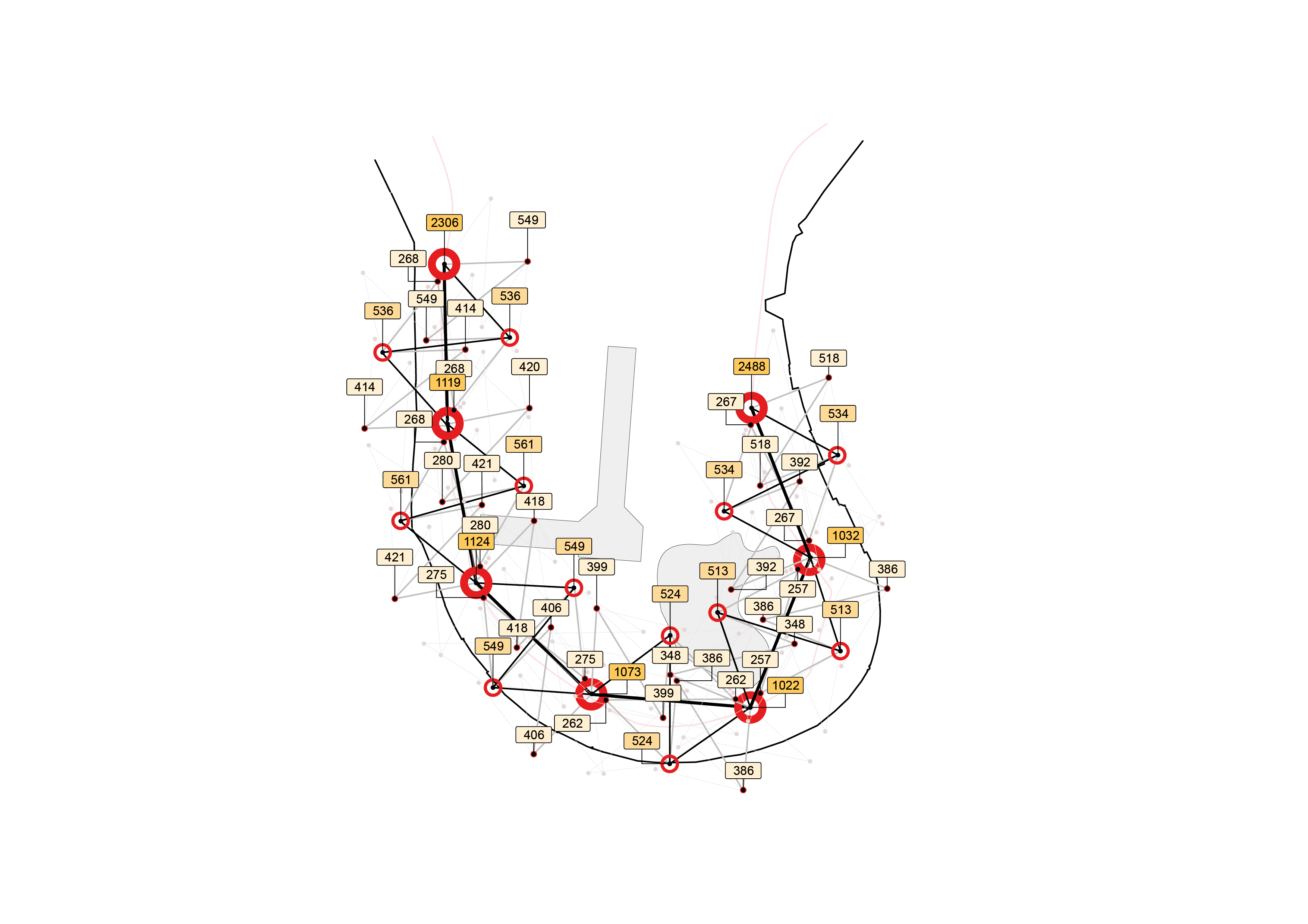
The initial site approach is to define some of the existing features of the peninsula which can serve as attractor points in the experiment. The U-shaped boulevard that goes along the Thames and around the Isle is selected to develop the new urban fabric. The red dots highlight some of the existing transportation hubs on site (i.e. bus stops, train stations, etc...) which can be regarded as anchor points in the urban algorithm. By adopting an existing spine for the fabric, one is able to weave the city within the bounds and with the constraints of the existing street pattern. Below is a diagram of the grasshopper parametric defintion used to generate detours in between two nodes or along a stretch of road of the urban tissue.
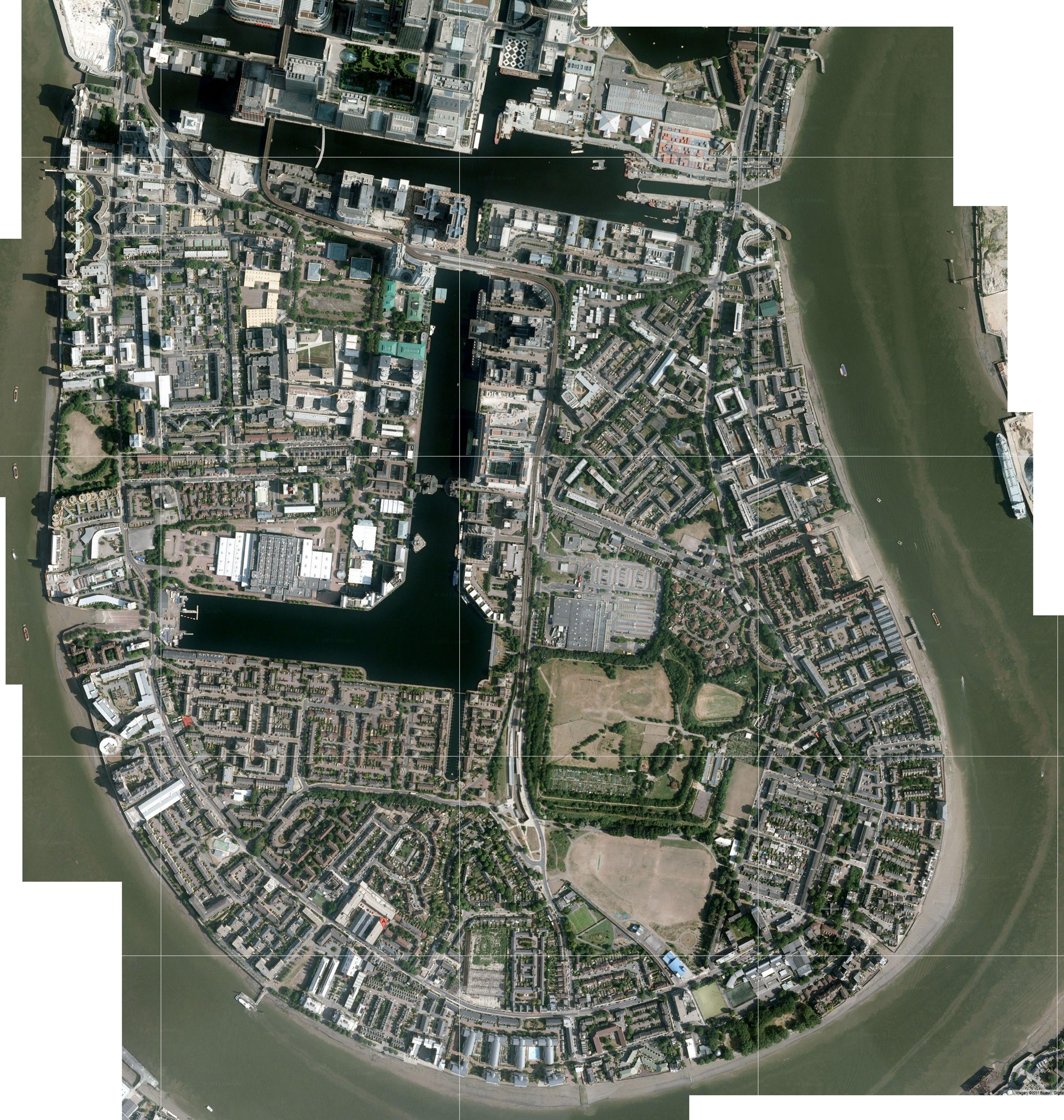
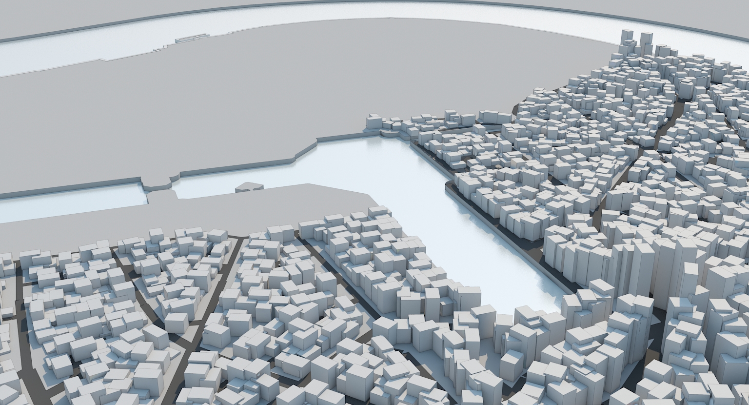
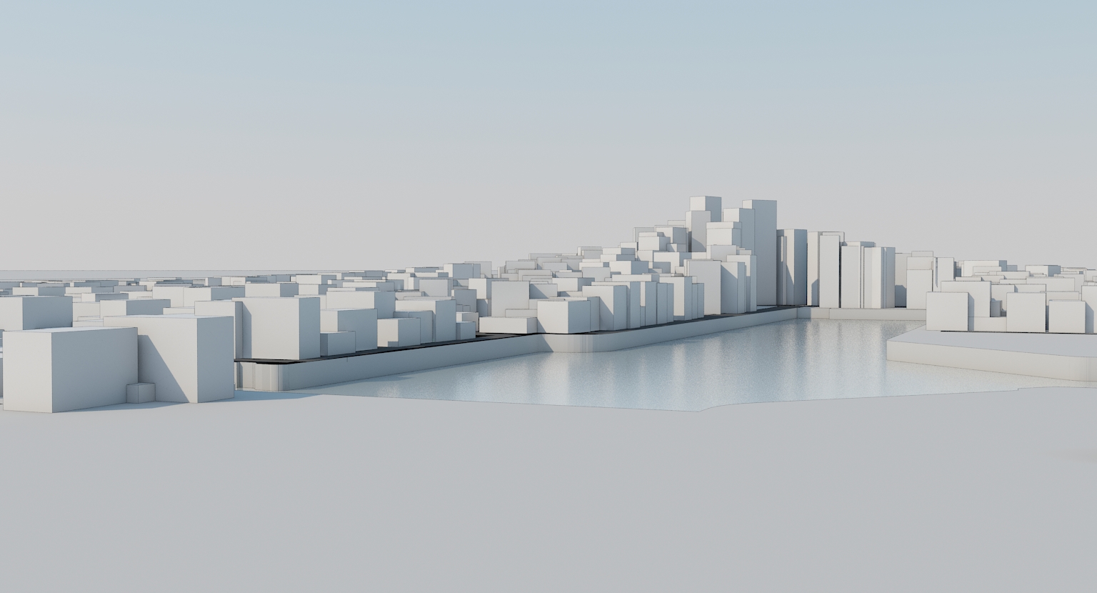
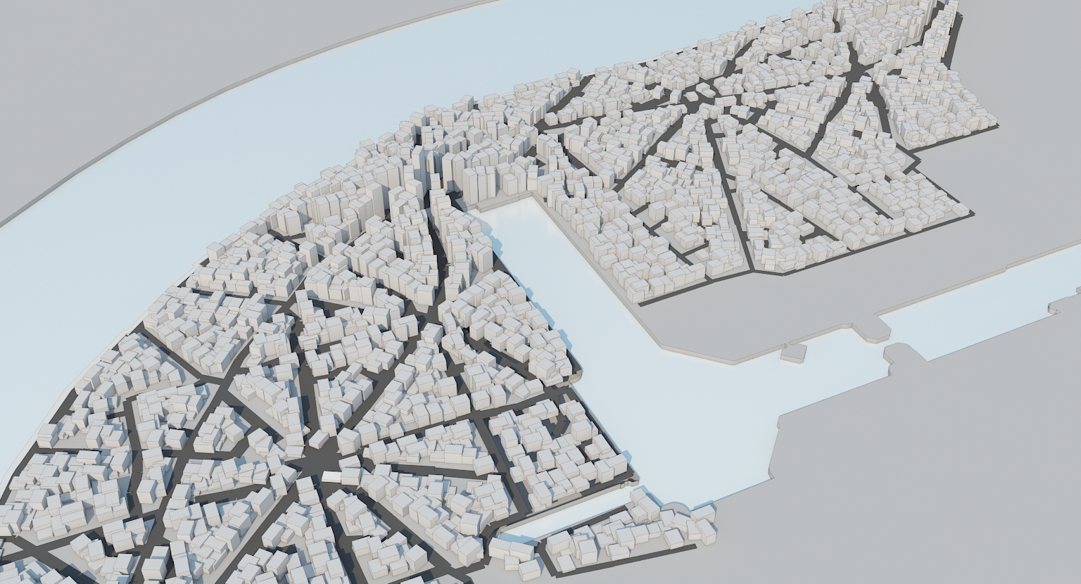
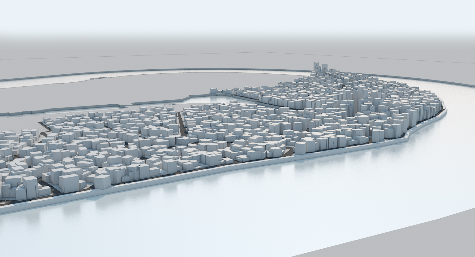
The project consists of defining and examining a patch of 1km² from the Isle of Dogs through a series of connected hierarchical scales. Just as biological and material systems operate at multiple levels of integrated organisation, the generated urban tissue is investigated at different operational scales and with specific micro-climatic, topological and social organisations. A set of associative rules are generated at the scale of the building, block and super-block which in turn produce unique structural, spatial, and programmatic effects. The site is located on the Isle of Dogs, south of Canary Wharf (below South Quay).
The initial site approach is to define some of the existing features of the peninsula which can serve as attractor points in the experiment. The U-shaped boulevard that goes along the Thames and around the Isle is selected to develop the new urban fabric. The red dots highlight some of the existing transportation hubs on site (i.e. bus stops, train stations, etc...) which can be regarded as anchor points in the urban algorithm. By adopting an existing spine for the fabric, one is able to weave the city within the bounds and with the constraints of the existing street pattern. Below is a diagram of the grasshopper parametric defintion used to generate detours in between two nodes or along a stretch of road of the urban tissue.
The project consists of defining and examining a patch of 1km² from the Isle of Dogs through a series of connected hierarchical scales. Just as biological and material systems operate at multiple levels of integrated organisation, the generated urban tissue is investigated at different operational scales and with specific micro-climatic, topological and social organisations. A set of associative rules are generated at the scale of the building, block and super-block which in turn produce unique structural, spatial, and programmatic effects. The site is located on the Isle of Dogs, south of Canary Wharf (below South Quay).
Script Structure or Pseudo code
Script Phase 1: Defining Pathways
The script starts by drawing the lines of pedestrian circulation based on the times of detour. The lines generated are necessary for later delimiting the lots. The parameters that the script uses at this stage are: the existing primary road, equally spaced division points or nodes along the primary road, an additional time for the detours.
Script Phase 2: Delimiting Plots
Detour lines now merge with the existing primary road to form the overall circulation network. The area of 1km² is now fragmented into a series of patches or lots.
Script Phase 3 : Adding Boxes
This part of the script consists of generating an initial population of boxes that stand for the buildings in the city. The adding of the boxes relies partly on the shape of the lots as each added box locates the closest stretch of road and orients itself towards it. But is also partly due to the way density is calculated in the script.
Why should it be oriented to the plot boundary? The reason is that if the building blocks aren't oriented, then the pathways get cluttered and sometimes, there are dead end pathways created and connectivity is lost.
In fact, the lots delimited previously are patches which can be converted into surfaces with U and V values. This helps subdividing the surfaces into orthogonal grids of points. The grids aren't necessarily all parallel, but they all share the exact same point concentration or compactness, and by inputting the number of points that need to be removed, one can decide on the urban density to emerge from the script. The definition combines all the points in one data stream then culls a certain number of them.
For example, 0 vertices culled result in a density of 100%, but randomly removing 30% of the vertices will not result in a density of 70% because many other factors come into place. Grid spacing or compactness gives further control over density as well as the footprint of buildings. We fixed our values to 250m² for the building footprint and 15m for the grid spacing, and set the number of culled vertices in a way to get a density of about 70% (percentage of built vs. non-built environment). In order to get more variety in the form of the boxes, another nested script is made to randomly generate various rectangular shapes of 250 m2 of area. The points created at this stage of the script constitute the seeds of the boxes.
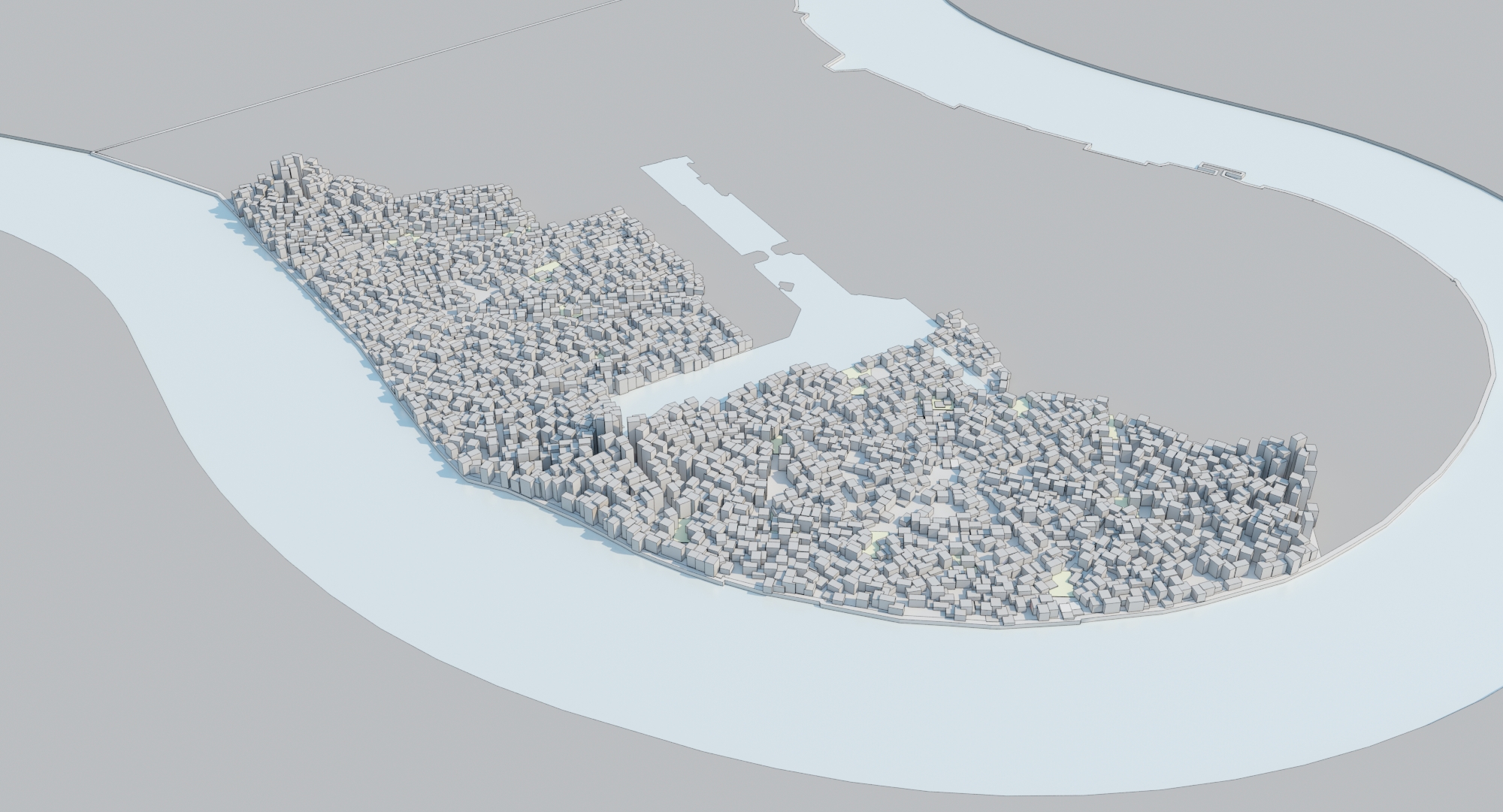
Script Phase 4: Box Packing
Once the boxes are created, their random dispersal leaves no space for the pedestrian activity to occur.
Roads so far are considered as non-physical entities that only represent the direction of the circulation without any consideration to width of the street. In order to distinguish the roads from the lots, boxes too close to the circulation axis are identified and pushed away, back into their lots.
A nested definition measures the distance of the buildings to their nearby road (d), and based on that value, pushes them inside their lots. Buildings very close to the street are pushed much further inside than those located in the center of the lot. In order to do that, the computer needs to compare the location of every building in the lot (d) to that of which is located most internally (dmax). So the operation for each building starts with a subtraction (dmax-d). From there, the resulting value is raised to the power of three (dmax-d)3, and controlled linearly with a slider (a). This calculation method allows moving the most external buildings considerably inward while keeping the most internal ones relatively in their place. The movement inward is achieved by a vector of amplitude a*(dmax-d)3, where (a) is the coefficient controlled manually. The packing logic results in an urban syntax which is clearly visible and hierarchical in plan.
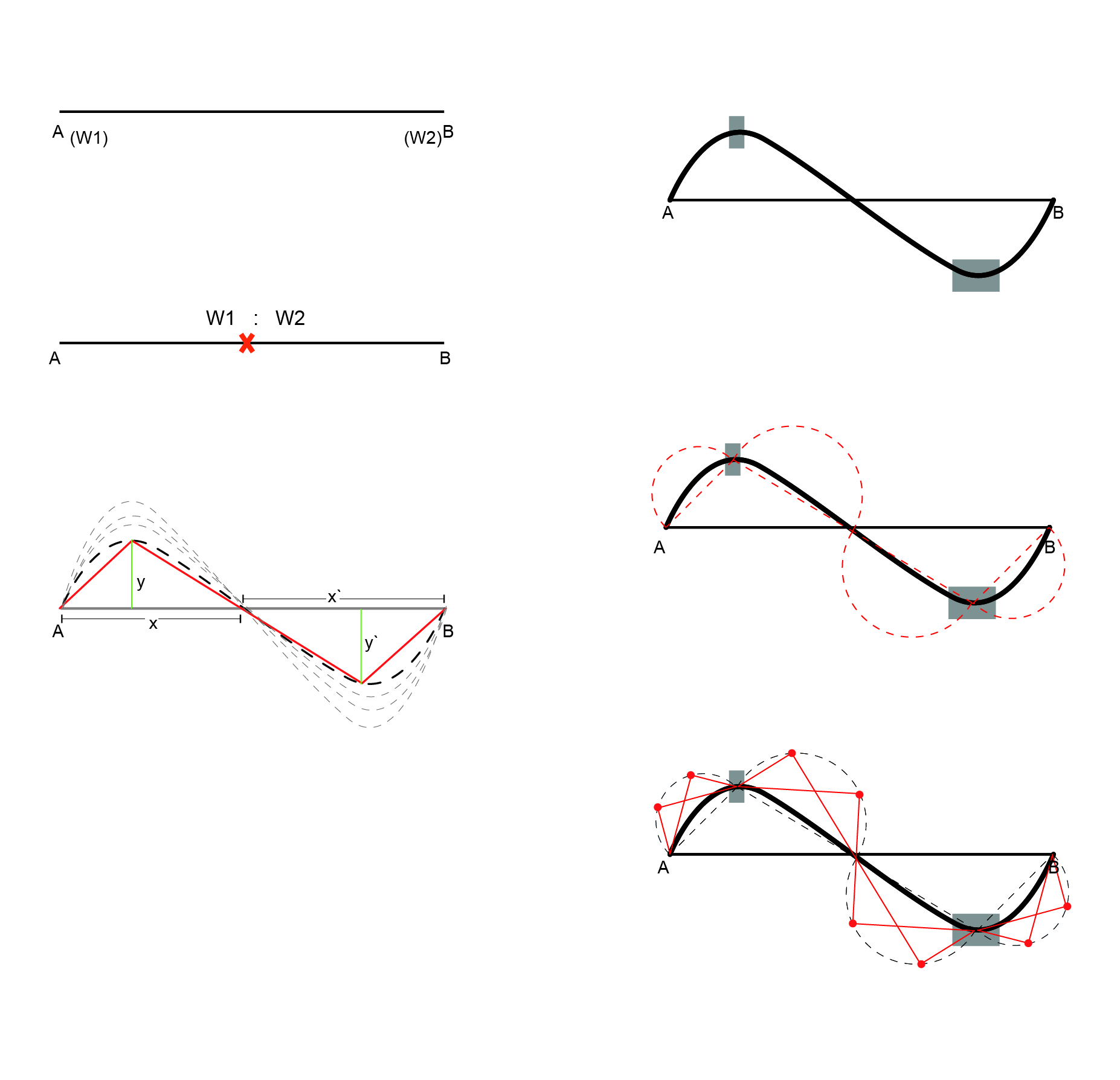
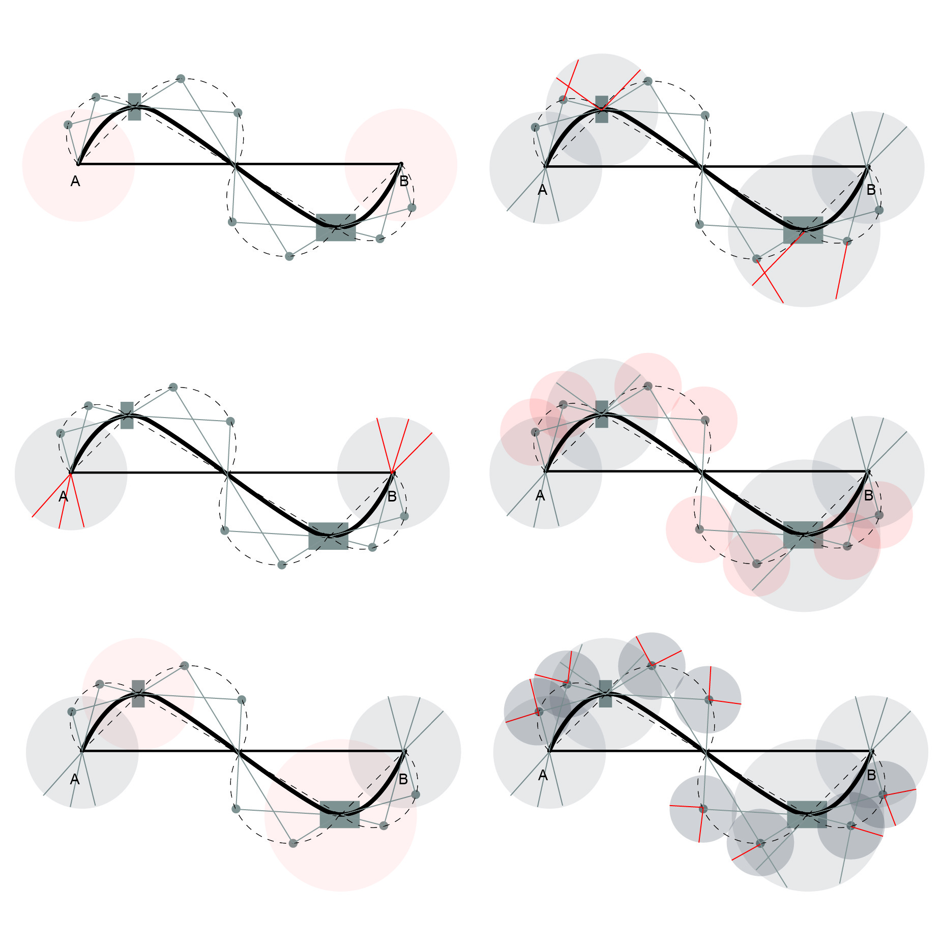
The way the script goes over this row of input values is by calculating the time of walking distance between a node and the next (t) and generating a deviant path across the primary road which shape is determined by adding a time difference (Δt) to each segment. The time needed for the detours becomes defined as (t+ Δt). The definition is designed in a way to give the exact shape of detour just from reading the time difference (Δt) at each segment of the primary road.
After the initial detour is achieved, open space is placed at the kinks. The size of the open space is determined by its proximity to the attractor points (dock and parks).
Circles as seen in the figure, is defined by diameter of length of the line connecting the nodes. This describes the limit of the secondary detour.
The number of pathways to be created within this can be 2 or more. The number would be influenced by the density requirements. Step 7 is then iterated for secondary and tertiary pathways.
At each of the nodes, there is circle of Influence defined by walking radius from that node. This defines the outer limits of the growth and starts delimiting the plots.

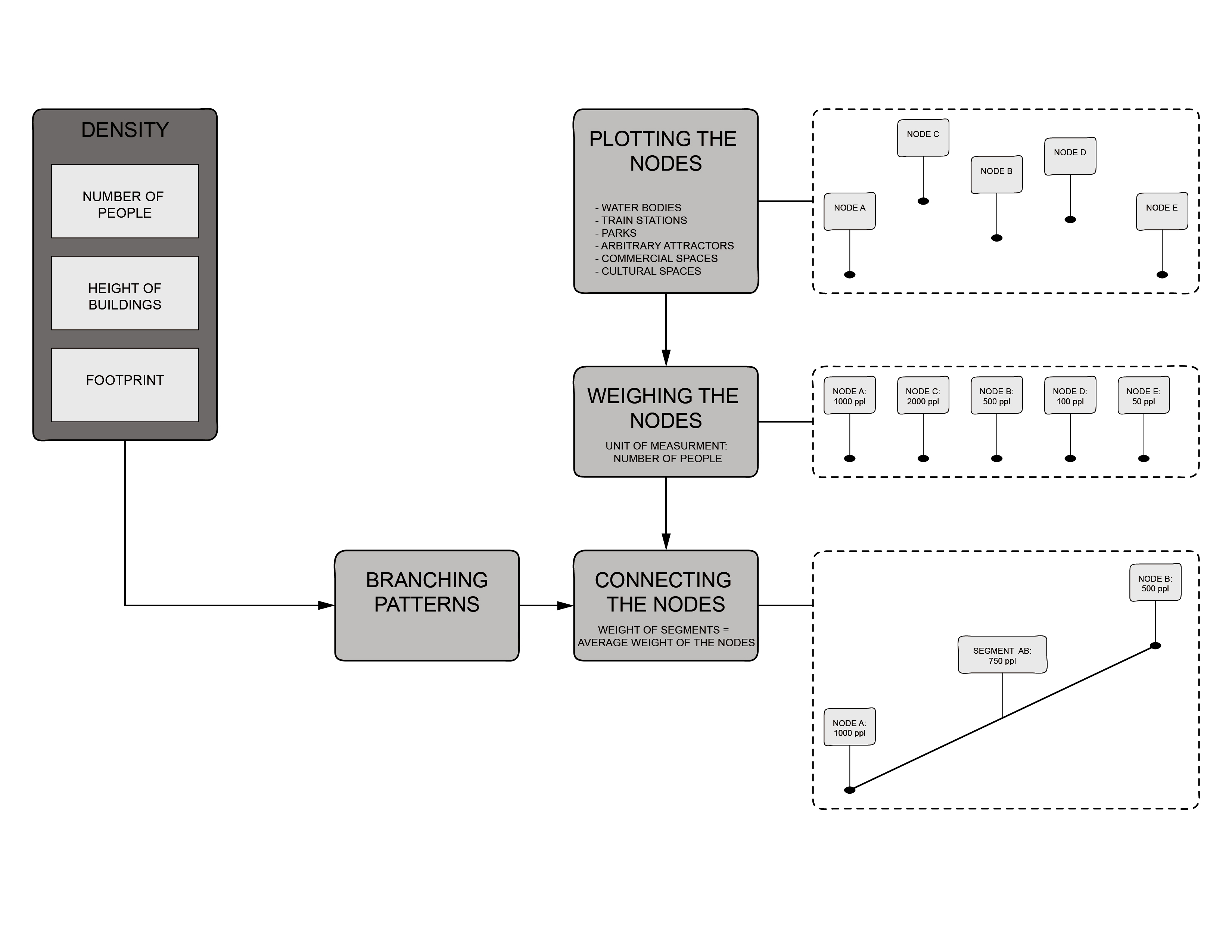
Influence of Density
After the Circle of influence has been defined, how does density affect the secondary detours.
Some of the options:
Option A - where the density doesn't matter and the number of secondary detour is two between pair of nodes.
Option B - Where the density is more, the number of detours can increase on one side of the pair of nodes in consideration
Option C - the width of the road varies when the density is high
Option D - Where density is high the number of detours increases but on both sides of the pair of nodes under consideration
Also the primary pathway’s width varies as per the sun direction. When the pathways are aligned along the northern sun, the roads are narrower. Diagrams on the right describe how the pathways vary with sun path direction.


Evaluation Criteria
The model is parametrically manipulated. It allows the time and form of the detours to be modified to reach reasonable lot sizes and proportions. Basically the parameters were modified until the model respected the following assessment criteria:
- The majority of the lots chosen are not too small (30000 m²). The benefit of keeping large lots, with areas up to 30000 m², is to allow for inner passageways to emerge.
- Small lots will have sharp street corners.
- Lot sizes should allow fitting clusters of 250 m² sized footprint buildings.
- Some pathways needed to be trimmed and others extended to cover the full extent of the 1 km² area and reach the boundaries of the site.
Option C was chosen as the pathways weren't to cluttered, and the plot sizes weren't too small.
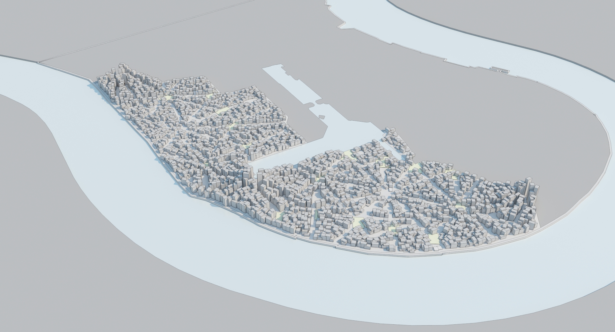
Sectional Typologies
The sectional typologies were developed from the series of sections taken from the previous model. Different sectional typologies are applied to the different hierarchy of the streets. The widths of the streets also vary according to the hierarchy.
The sectional typologies were developed from the series of sections taken from the previous model. Different sectional typologies are applied to the different hierarchy of the streets. The widths of the streets also vary according to the hierarchy.
Width Range
Primary : 15m – 60m
Secondary: 20m 48m
Tertiary : 3.7m – 33m
Primary : 15m – 60m
Secondary: 20m 48m
Tertiary : 3.7m – 33m
Each section is placed along the street and has the ability to modify their dimensions inside a certain range. The image shows the basis of each section, and the algorithm includes a variation of height in a range +/- 2 floors and the horizontal dimensions in +/- 5 meters. The building depth is fixed as 12m, to assure an optimal use of the building.

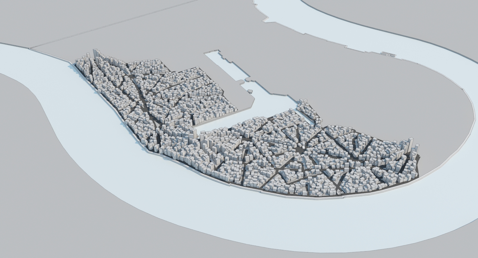
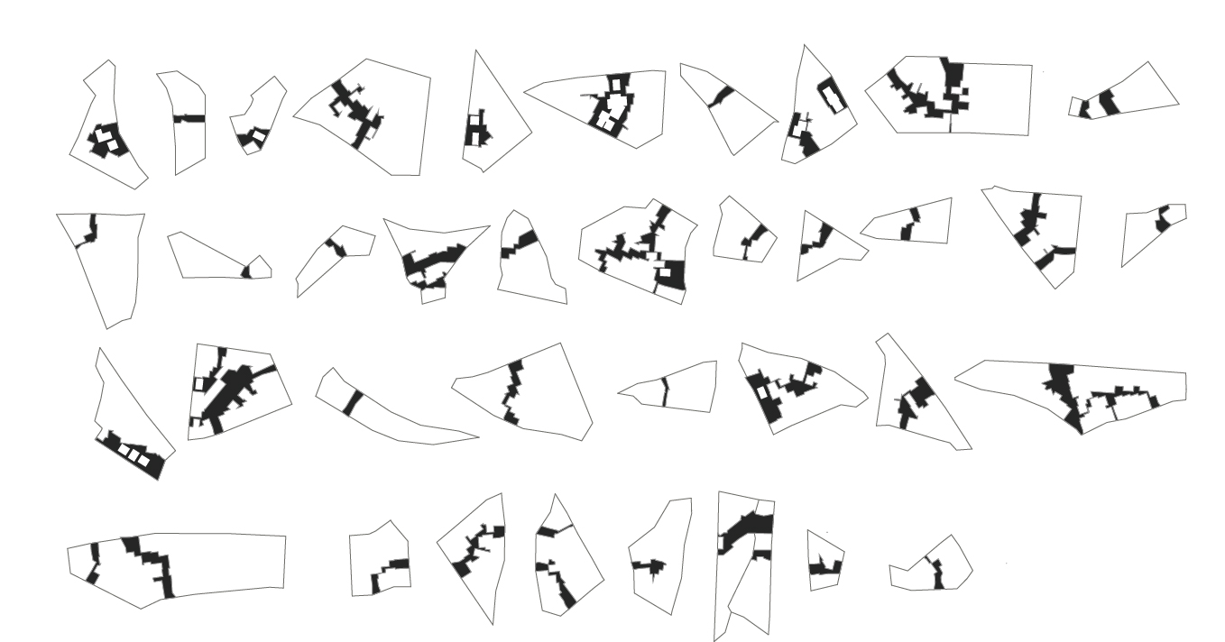
The tertiary streets are the emergent pathways created by the random distribution of the building blocks. Due to this randomness, not only the spatial configuration but also the direction and pattern of these pathways are different. From all of the urban blocks, only 60% of the blocks appear to have emergent pathways. These tertiary streets are considered to be crucial in defining the hierarchy of street integration based on the space syntax analysis. The model D used in the space syntax analysis showed the clearest distinctions among the hierarchy of pathways, and the wide range and clarity in hierarchy demonstrated in this example served as the precedent to carry out the further experiments.
From all of the tertiary pathways resulted from the first experiments, six typologies of the emergent pathways were found in the plan shape. These are to serve as the gene pool for the shapes of the tertiary roads. The intention for the further experiment is to select 60% of the urban blocks generated by primary and secondary roads and apply the tertiary streets randomly chosen from the gene pool of typologies.

Architectural Association
Emergent Technologies & DesignCore Studio
2012